Connecting an RFM69 Radio to a Raspberry Pi
This blog post is in two parts. In this part we cover how to physically connect an RFM69 radio module directly to an Raspberry Pi’s (RPI) SPI bus. The companion post covers how we can listen in to the Radio using some of the nice new features in Python 3.
So let’s get started. Below is a list of all the components I used and links to where you can get hold of them. Don’t feel constrained to using the brands I have used. Many different companies produce RFM69 breakout boards and they are all much the same.
Componants
-
A Raspberry Pi 3. I have only tested this myself on a RPI 3, however it will no doubt work on any other Pi. I am pretty sure the wiring is the same for the RPi 2B+ onward (inc the Zero).
-
Adafruit RFM69HCW 433Mhz (UK freqency) which you can buy from PiHut for about £10. Note: This is the high power version which will draw more current than an RPI can supply when it is in high power mode. So we will reduce the transmission power in the code. Why buy the HCW model then? Well you may want to reuse the radio later in another project and the price differences is nominal.
-
Prototyping PI Hat. I bought one from Hobby Components for £4.50, but any prototyping hat will do. You could even make a board yourself.
-
Additional Antenna. I had one lying around, but you can use a piece of wire. For the 433Mhz setup it needs to be 16.4cm long. For more on antenna options check out this explanation by Sparkfun.
Wiring
The pins of the Raspberry Pi can be confusing and figuring out which pin is the right one and which one is going to make a loud popping noise can often mean repeated counting. If you struggle, like I do, to mentally map from diagrams to the real world then I suggest buying or downloading a template card (a.k.a. a leaf).
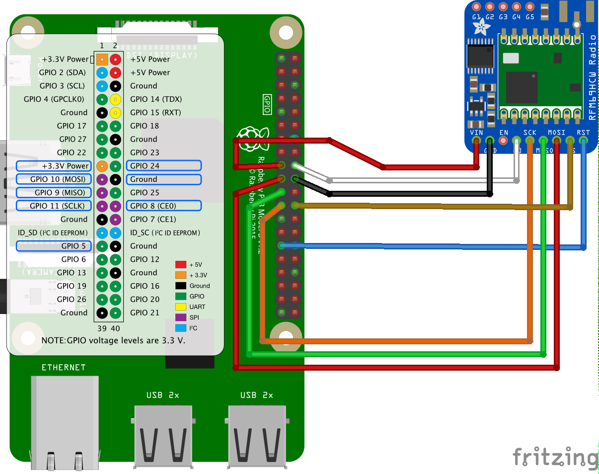
So that is how we are going to connect it all up. Different makes of breakout board use different terminology. For example the Sparkfun boards use NSS rather than CS and DIO0 instead of G0. The table below is my best effort at making the wiring clear. If you come across any different terms then let me know and I will include them.
| RPI Name | 3v3 1 | Ground | MOSI | MISO | SCLK | CE0 | ||
|---|---|---|---|---|---|---|---|---|
| PPI GPIO | GPIO10 | GPIO9 | GPIO11 | GPIO242 | GPIO8 | GPIO5 | ||
| RPI Pin number 3 | 17 | 25 | 19 | 21 | 23 | 18 | 24 | 29 |
| Adafruit RFM69HCW | Vin | GND | MOSI | MISO | CLK | G0 | CS | RST |
| Sparkfun RFM69HCW | 3.3v | GND | MOSI | MISO | SCK | DIO0 | NSS | RESET |
Notes:
- This pin cannot support full power. Use different supply if you want to use the RFM69HCW at full power.
- This is the interrupt pin. The RFM69HCW module calls an interrupt on the RPI when there is new data to process.
- These numbers refer to the pin’s location, indexed from top left to bottom right. The Pinout.xyz is an amazingly helpful tool.
Testing
Before you go soldering everything in it is a good idea to test it out on a breadboard. I bought one of these breakout adapters from Amazon for about £6 and it makes testing super easy.
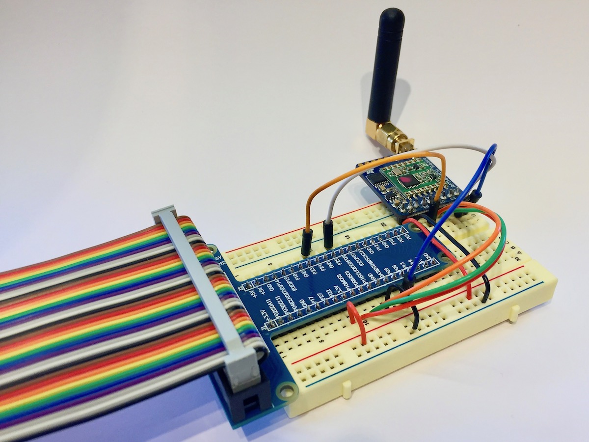
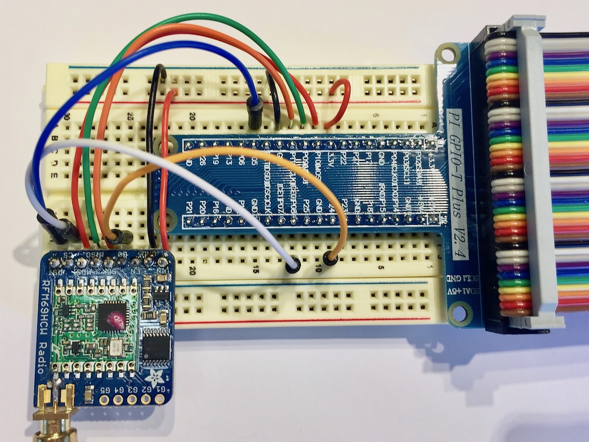
Checkout my companion post to see how to get the code up and running on the RPI. Then you can test the components and make sure all is working well before you solder things in place.
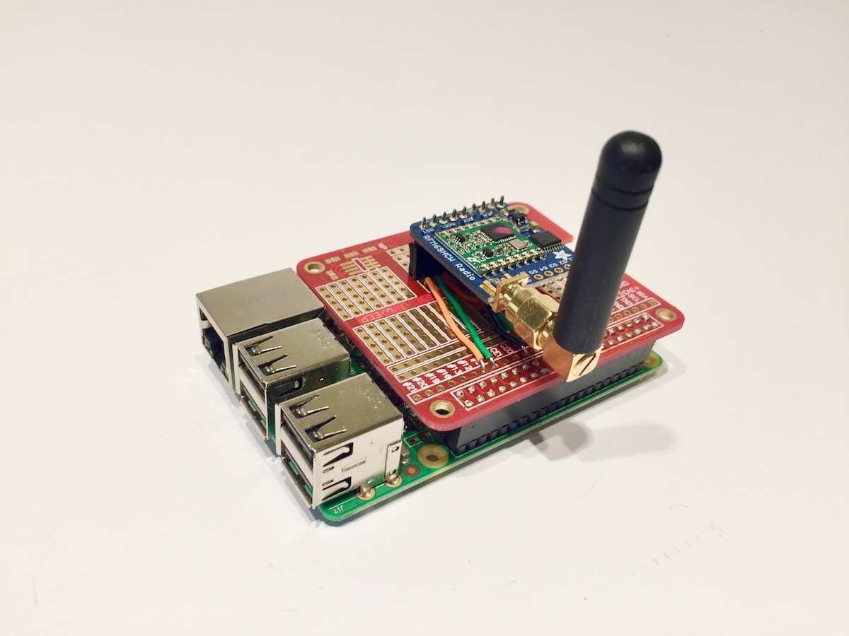
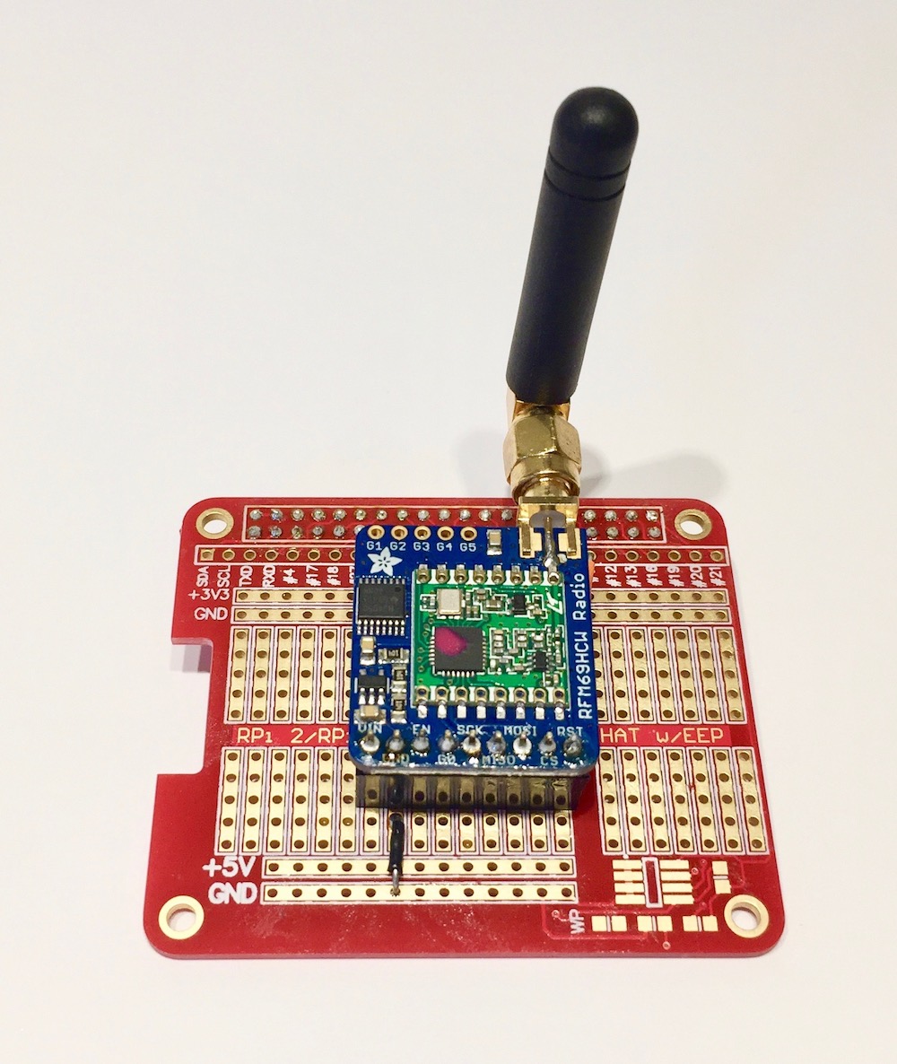
End product
Finally you can transfer the wiring to a Prototyping shield (see images below). I used male and female headers to connect the RFM69 module to the board, so I can easily remove it for another project.
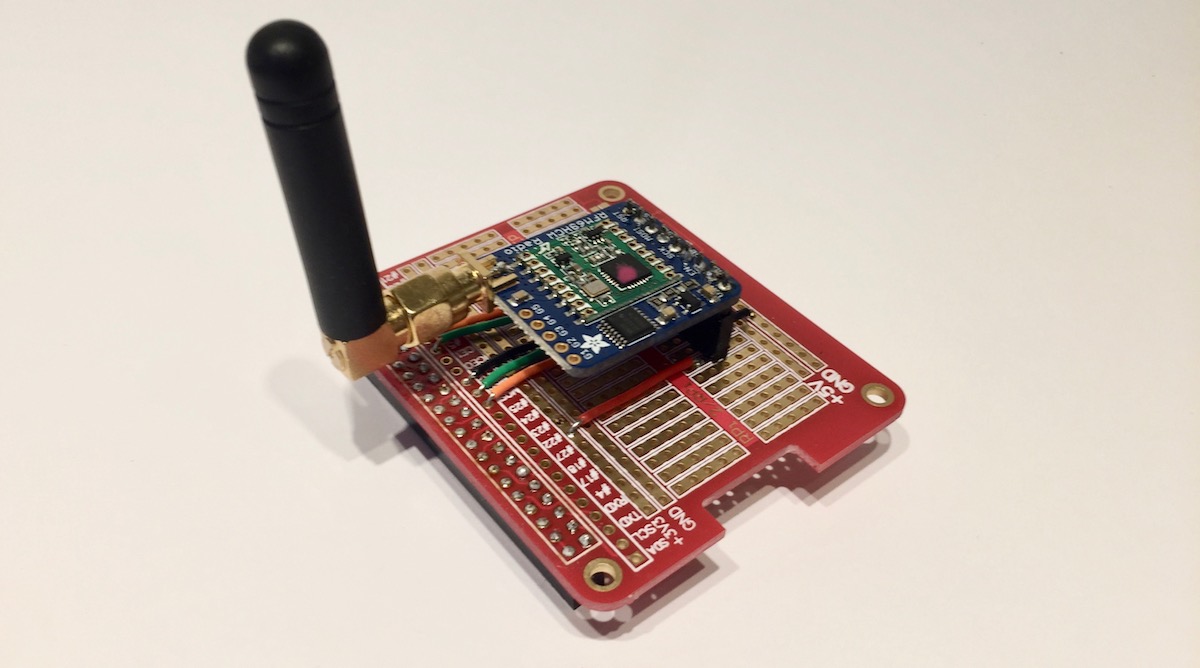
Having written up this tutorial I found a series of posts from Jeelabs. They made their adapter board which doesn’t use an RFM69 breakout board, so its really compact.
